CDN NEWS |
  US NEWS


![]()
Overview
Part 3 of this series presented the data set and calibration used to characterize C-0.5Mo performance. This part extends the calibration to Carbon Steel using the same basic calibration procedure. Unlike C-0.5Mo where carbon activity was used as the calibration parameter, for Carbon Steel the carbon activity is assumed to be 1 in all cases. Variability is then expressed in terms of actual life vs. predicted life. Results of the analysis show that 90% of the data is captured with the basic model and parameters given in [1], and that 81% of the data is conservatively captured within a factor of 10 on life. This magnitude of variability is typical for creep and fatigue data and is therefore considered quite reasonable. With this basis, average and minimum Carbon Steel Nelson Curves can be constructed, which are presented in the next part of this series.
Available Operating Case History Data
Data for this analysis are taken from API RP 941 [2] and it’s basis document [3], supplemented with short term data from Weiner’s experiments [4]. All told this represents 52 total points with enough information to attempt a through-wall fit. Unlike C-0.5Mo, there is very little information available for most points, even within the background files. The exception are the more recent as-welded failures that have prompted revision to both [2] and [3]. The focus here is then on conservative assumptions to fill in missing or uncertain data, which would tend to make results pessimistic.
The make-up of the data set in terms of temperature, hydrogen partial pressure and operating duration is shown in Figure 1 and Figure 2. The figures again break up the available cases into:
- Base Metal (remote from weld/no weld residual stress influence): 31 points
- PWHT (near weld, PWHT-level weld residual stresses): 4 points
- As-Welded (weld region, full weld residual stresses): 17 points
There is again a range of damage in these 52 points, though all represent some level of attack. Results for no attack, while not presented for brevity, are however in line with a factor of 10 on life. What is immediately apparent from Figures 1 and 2 is that most of the data is for short times – in fact, only a single base metal or PWHT point exceeds 10 years of operation, and only just so (11 years). This is illustrated in histogram format in Figure 3. The shortest duration points come from lab tests with varying amounts of detail, although none of the data has detail even approaching that of [5], and as such there is more uncertainty (and likely conservatism) associated with this carbon steel analysis relative to the previous C-0.5Mo analysis presented in the last part.

Figure 1: Temperature-Partial Pressure Make-Up of Data

Figure 2: Temperature-Time Make-Up of Data

Figure 3: Operating Duration for Carbon Steel Data Set
Calibration Procedure
The calibration procedure is the same as described in the last part for C-0.5Mo. As discussed in the last section, calibration is based on as-welded, PWHT and base metal conditions, which correspond to different WRS levels (100%, 30% and 0%, respectively) and for the as-welded case, an increased dislocation density in the low temperature creep term along with a modified/lower creep exponent. All as-welded failures were again crack-like and occurred in the weldment region (typically the HAZ). An example of such a case is shown in Figure 3.
There are very few cases (4) where PWHT is considered to have been likely, though one of these did have crack like damage. For consistency and conservatism then, the PWHT and as-welded cases are again assumed to “fail” when 100% damage reaches 25% of the wall. For base metal removed from any welds 100% damage to 50% wall is again used. Note that for the lab specimens (all full immersion) surface damage and through-wall damage are the same. Additionally, lab specimens that were pre-charged with hydrogen assume a uniform void spacing of 0.95 mm regardless of temperature.
Allowable stresses and yield strengths correspond to the actual specification (e.g. SA-106 Gr. B, SA-516 Gr. 70, etc.) and depend on temperature as described in a previous part of this series. Also recall that the WRS is taken as minimum yield at the given temperature plus 10 ksi. Based on the low temperatures of all as-welded cases, no WRS reductions are made.
For cases where it was not clear if damage was at a weld or not, a conservative first pass was to assume the damage was well away from any welds (0% WRS). If this result could not reasonably bound the behavior, then PWHT (30% WRS) was assumed.

Figure 4: Example of Local Crack-Like Damage for As-Welded Case
Results
The overall results of the calibration are presented in terms of factor on life (predicted/actual) in Figure 5. Note that there are two cases which fall outside of a factor of 2 on life on the unconservative side (which will be presented and discussed in the next section) but that the remaining data is easily captured within this range. Figure 6 shows that 90% of the data is conservatively captured with the basic model and parameters given in [1]. Of that data:
- 43% is within -2x on life

- 79% is within -5x on life

- 89% is within -10x on life

The one as-welded outlier that is just beyond -20x on life is API RP 941 plotted point 37 – while this single point may just represent extremely excellent performance (easily captured by the model), it seems possible that temperature and partial pressure could’ve been reported as design rather than operating. While certainly anecdotal, the scatter seems to be smaller for the cases with the most information available (such as as-welded points 35).

Figure 5: Carbon Steel Calibration Results (1)

Figure 6: Carbon Steel Calibration Results (2)
Review of Outliers
With reference to Figure 5, two points are found to be unconservative on predicted life by about a factor of 4. The first of these points is API RP 941 plotted point 20A (Incubation Point L). The available information for this point is shown in Figure 7 where it’s reported that an isolated piece of pipe was “attacked to 27% of it’s thickness after 5745 hours”. Since this point was reported as part of the 1957 survey, it’s assumed that the damage was significant (as opposed to isolated voiding detected with SEM). The nature (crack-like? distributed volumetric?) or location (HAZ? remote from Weld?) of the damage is not known, so results for all three assumptions are presented in Figure 8 (through-wall) and Figure 9 (Nelson Curves).
As shown, only the as-welded assumption captures the point. While the damage may have been crack-like and near the weld (in which case the prediction would be conservative) the more limiting PWHT assumption is kept to highlight the general approach and likely conservatism taken in the calibration. With reference to Figure 9, note that the point is in the vertical portion of the predicted curve, such that any possible discrepancies in temperature wouldn’t change the result. Similarly, the partial pressure would need to be 1.7 times that reported for the prediction to match the failure time.


Figure 7: API RP 941 Plotted Point 20A/L Basis

Figure 8: API RP 941 Plotted Point 20A/L Through-Wall Results
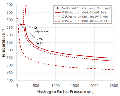
Figure 9: API RP 941 Plotted Point 20A/L Nelson Curve Results
It’s therefore assumed the most likely explanation is that stresses where higher than PWHT plus allowable levels locally (such as for as-welded, or due to piping loads, stress concentration factors, etc.) or that local damage was exacerbated by other defects. This last case allows for damage to truly be accelerated relative to the model without the result being unconservative from a through-wall failure perspective; see for example MPC-11 in Part 2 of this series.
The other outlier shown in Figure 5 is from a very well-documented case [6] and corresponds to API RP 941 plotted point 19 (Incubation Point B). This case is referenced as a weld toe failure because there was a weld-zone crack at the top head. The crack was at a major thickness discontinuity between the shell and head with stress concentration factors (SCFs) noted from an improperly ground weld. While there was some hydrogen damage (which thwarted repair weld attempts), it’s difficult to characterize this as an HTHA failure (at the weld) due to the significant (and un-characterized) SCFs present.
However, and more interestingly, wide-ranging base metal attack was characterized as well, which is what is actually used for the calibration presented here. The material in question is A201-B (60 ksi tensile strength) which had typical (actual) yield strengths of 35-38 ksi [7]. The vessel had a wall thickness of 1.625 inches which means PWHT is likely, although the damage is known to be volumetric and distributed. Wall temperatures varied substantially and were reported through-out the year – an example from [6] is shown in Figure 7.

Figure 7: Ciuffreda and Rowland 1957: API RP 941 Plotted Point 19/B
In the “Attacked Metal” region, decarburization was noted all the way through-wall with extensive fissuring to 0.75 inches (46% wall), although there was no through-wall failure. The through-wall model results for different elevations are shown in Figure 8 for both the base metal and PWHT assumptions. Both predictions would underpredict the deepest extent of damage, but capture the variation in degree of damage with elevation relatively well. When viewed in Nelson Curve form (for PWHT assumption), Figure 9 shows that the behavior for the majority of the elevation is captured extremely well, and it’s only the depth at the highest temperature that is underpredicted. Specifically, the un-damaged 575°F region is predicted to show no observable damage after 1 year (just above 5% at surface/highest pressure location), while the 640°F and 705°F regions are predicted to show increasing through-wall damage with temperature (5% and 25%, respectively) which matches the available information well.
For the 765°F location, not that there is substantial 100% damage depth predicted even for the 0% WRS (base metal) case. When viewed as a whole, the model prediction is actually considered very reasonable, and it’s likely that results at the highest elevation were affected by thermal stresses (not considered), or perhaps greater hydrogen penetration from excursions to higher temperatures (which did in fact occur) subsequently trapped at lower temperatures.
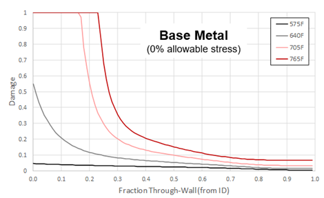
Figure 8: Through-Wall Damage Prediction at Different Elevations for Point 19/B

Figure 9: Point 19/B Results: Nelson Curve Format
For the two outlier cases just presented (both less than a year and both seemingly impacted by applied stress levels), the model performance is considered quite reasonable given the uncertainties and sometimes extremely limited information available. This is particularly true when considering these two outliers represent less than 4% of the total data.
Summary
This blog has presented analysis of fifty-two Carbon Steel lab and industry data points in terms of predicted vs. actual time to failure. As shown the basic model captures the vast majority of the data conservatively. The model performance for the small amount of data (less than 4%) where the prediction was approximately 4 times longer than the reported actual is considered very reasonable based on the detailed discussion given here. With this basis, time-dependent Carbon Steel Nelson Curves can be generated with confidence, and as shown in the next and last part of this series, still match the existing Nelson Curves extremely well for the representative time of 200,000 hours.
becht.com
References
- Dewees, D., G. Buchheim, J. Staats and C. Becht V, “Practical HTHA Experience and Time-Based Nelson Curves for Improved Equipment Life Management,” Inspectioneering, V(26)-2. March/April 2020.
- API Recommended Practice 941, “Steels for Hydrogen Service at Elevated Temperatures and Pressures in Petroleum Refineries and Petrochemical Plants,” Eighth Edition, February 2016. The American Petroleum Institute.
- API Technical Report 941-A, “The Technical Basis Document for API RP 941,” Addendum 1, June 2019. The American Petroleum Institute.
- Weiner, L. C., “Kinetics and Mechanism of Hydrogen Attack of Steel,” Corrosion, 1961, V17, p. 109.
- Peng Liu, “Fundamental Studies of Hydrogen Attack in C-0.5Mo Steel and Weldments Applied in Petroleum and Petrochemical Industries,” in Department of Material Science and Engineering, 2001, The University of Tennessee (Doctoral Dissertation).
- Ciuffreda, A. R. and W. D. Rowland. “Hydrogen Attack of Steel in Reformer Service,” 1957. New York: American Petroleum Institute.
- ASTM Data Series DS 11S1, “An Evaluation of the Elevated Temperature Tensile and Creep-Rupture Properties of Wrought Carbon Steel,” by G. V. Smith. American Society for Testing and Materials, Philadelphia, Pa. 1970.
Share This: